Vactrol Breakout
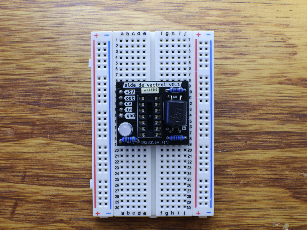
last updated: Mar 14, 202314-mar-2023 > proto 0.1 boards arrived, and assembled! photos 2-mar-2023 > proto 0.1 boards ordered, stay tuned
This little PCB breakout is set up to be used an re-used, for prototyping, or modular designs. It's kinda nice because you can just care about the 5-pin header and the rest of the vactrol circuit is just kinda taken care of.
The values for the resistors are all blank because you have to adjust them a bit. I'll fill in some values as I find sweet spots for the vactrols on hand. (And some of those will for sure be home-made!)
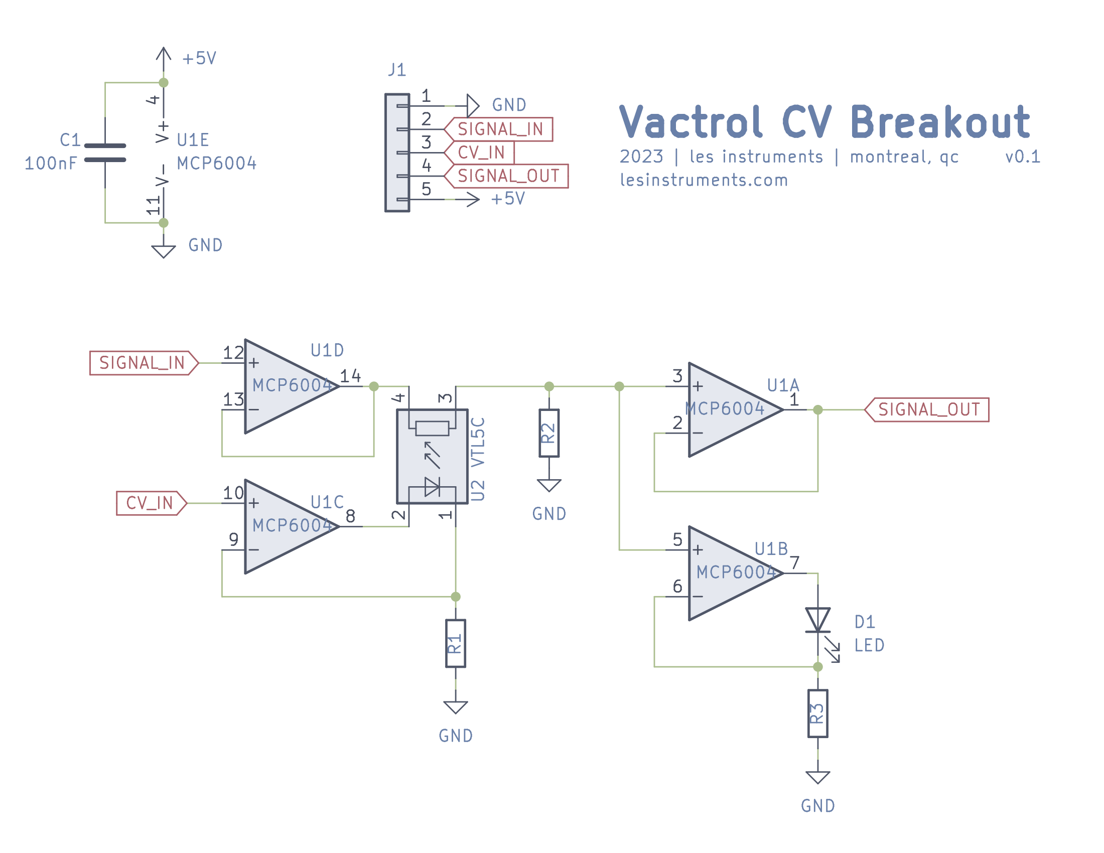
This design uses an MCP6004 since it can go rail-to-rail, and given some designs it's useful if you've already got a 5V power rail from a microcontroller or something. Pin-wise you could totally drop in a TL074 and that'd probably be fine. You'd really have to figure out the R values because you'd be dealing with larger range of voltage.
Although not perfect, it seems like a decent option that will at least provide a bit of stability and consistency to most simple designs that use it.
Info
- input signal from 0-5V
- CV input from 0-5V
- output signal from 0-5V
- a buffer on the input signal, so it won't mess with anything upstream
- a linear configuration for the vactrols' LED (see: article, simulation)
- output buffer
- signal output LED indicator
caveats
- your cv will be limited to the power rails of your op amp (and also the limits of your op amp, so beware you can fry it)
- negative voltages might do weird things or fry your op amp
- there is NO protection in this circuit
- you'll probably want pulldown resistors on the inputs
Schematic
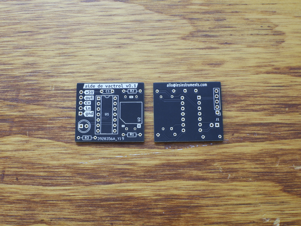
v0.1 Boards