Barebones Eurorack power
last updated: Jan 31, 2023Check out version 2
Check out this article from Division 6 about the basics of Eurorack Power for a terrific jump off point. They lay it out real nice.
For my purposes, I chose to follow this pattern. However, I wanted a semi permanent solution and wanted to test making a PCB using EasyEDA and JLCPCB. This seemed like a good project to try some new things!
I also went this route because I only needed two regulated[1] wall wart power supplies (which are pretty easy to find, and about $15CAD each) and a very basic circuit to make it easy to hook them up to my circuits and prototypes.
The goal is to have a power solution that can output + AND - 12 Volts, with ~1A per power rail. (My wall warts give me 2A on each +12V and -12V) 🥳. Plenty of current for a few modules! (For example, an Arduino's max current draw is ~200mA.)
Bill of Materials:
- 2x regulated 12V DC Wall Wart Power Supply
- some stripboard with at least 8 rails
- some snappable pin headers
- 2x 2.1mm DC jack plugs
- 2x LEDs
- 2x 1K Resistors
- as many eurorack cables as you need
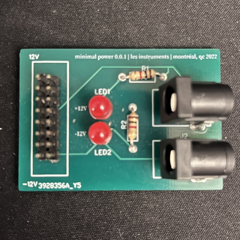
Hey hey hey, they're backward!
Sure, there are maybe cheaper or more efficient ways to do this, but this is pretty practical and widely available in terms of options. And yes, those DC Jacks are most definitely backward. Growing pains are real but pretty laughable at this scale. I'll try to be more careful going forward but I'd bet the farm on this not being the last mistake I make like this.
This solution worked for a bit until I had finished my second module on a breadboard and wanted to make the two of them interact. It was time to make a simple busboard to distribute the power rails! I soldered together a quick passive busboard with a few male 16-pin connections, allowing more than one module to be powered at a time sharing the same power supply.
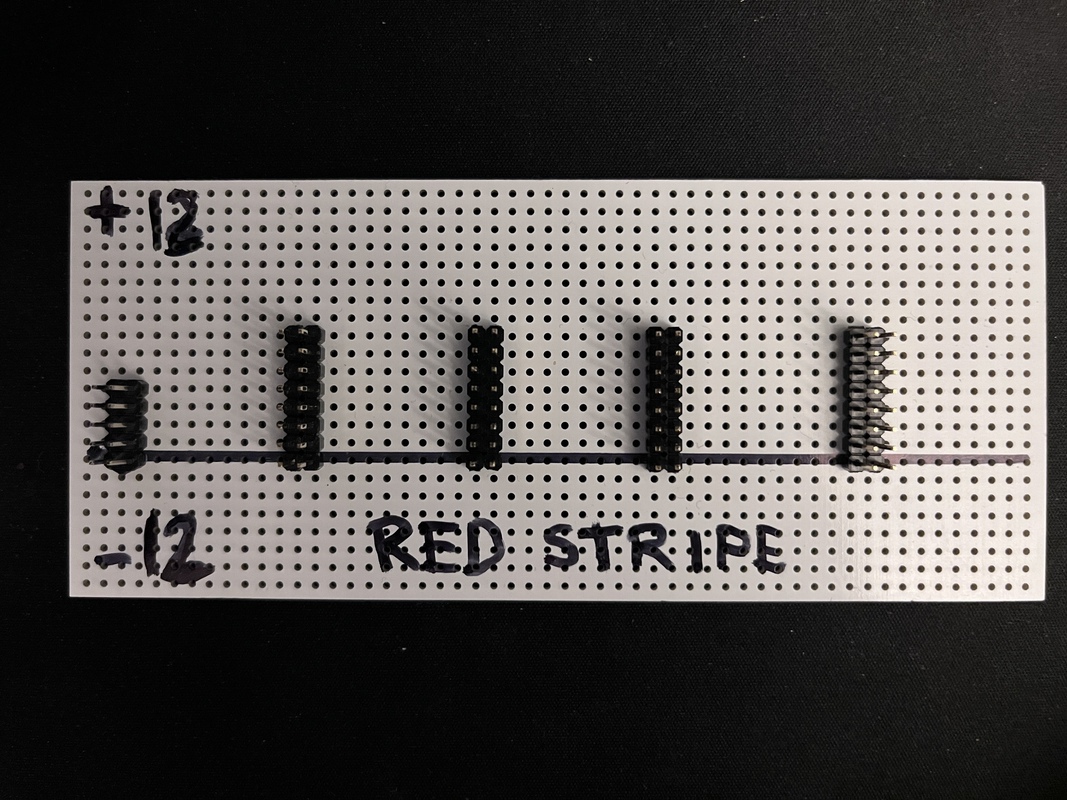
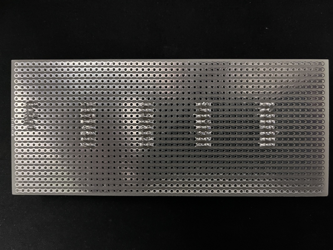
After that, I can just use a bunch of 16-pin -> 10-pin cables to connect the busboard to the modules and forget about any shared 5V, CV or Gate rails (most commercial eurorack modules don't use them either). I plan to pop in 5V regulators onto the modules where needed, and allow the module to regulate the voltage to its own needs.
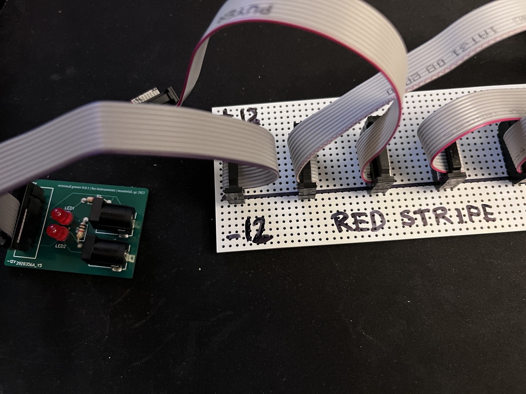
Version 2
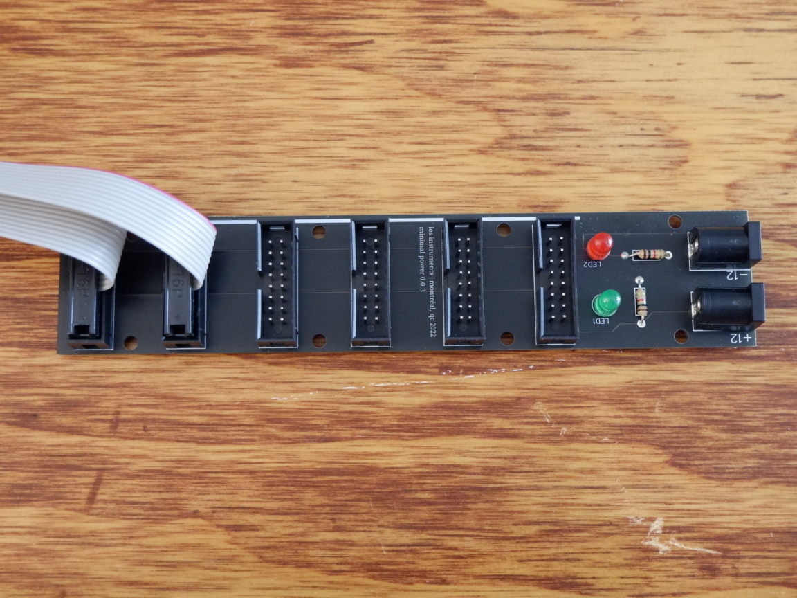
This time with the DC jacks facing the right way, and a small busboard (6x16-pin connectors) included. Still works just fine, still feels hacky, but good enough to power some simple DIY stuff without really worrying too much.
Potential improvements
- ✔️ Fix the backwards DC Jacks 😂
- Add some reverse polarity protection
- ✔️ Combine a busboard with the DC Jack portion into one simplified board or PCB
Cut the stripboard I guess to save material but I kinda like having more space (If I don't go with the above)
==============
Footnotes
[1]: Just make sure the wall warts are actually regulated, as cheaper ones usually aren't. You can check with a multimeter, a regulated supply should have a nice constant voltage right around the specifications. An unregulated supply's voltage would likely be higher than the specification, as well as potentially irregular.